Ordered, immediately called back and the same day delivered the order.Very pleased with the work. Thank you for prompt and accurate work https://africarx.co.za/ great prices, delivered on the day of the order. Pleasant managers consult by phone.
Unistream.estb.com.sg
INSTALLATION, OPERATION & MAINTENANCE INSTRUCTIONS FOR EBSRAY MODEL HD600 ROTARY INTERNAL GEAR PUMP PTY.LIMITED ACN 000 O61 003 PITTWATER BROOKVALE AUSTRALIA PH: (61 2) 9905 0234 FAX: (61 2) 9938 3825 SECTION 1 - GENERAL INTRODUCTION 1.3TRANSPORTATION AND PACKING Standard domestic packing is suitable for shipment in
This leaflet is intended to assist those involved with the
covered transports. Ports must be sealed to exclude
installation, operation and maintenance of EBSRAY
ingress of solids. When received on site the pump should
Model HD600 Internal Gear Positive Displacement
Pump. The design, materials and workmanship
If storage is required for other than a short period prior to
incorporated in the manufacture of EBSRAY pumps
installation, special preservatives and protective
make them capable of reliable operation over a long
wrappings will be required. Refer to EBSRAY for details.
working life. Correct installation is essential. Service life is enhanced by periodic inspection and careful
1.4INSPECTION ON RECEIPT - SHORTAGES
On receipt of equipment, check all items against the
1.1CAUTION
dispatch documents and inspect for damage. Any damage or shortage incurred during transit should be
INSTALLATION AND SERVICING OF THIS
noted on the packing note and on both your own and the
EQUIPMENT SHOULD BE PERFORMED BY
carrier's copy of the consignment note and a claim
QUALIFIED COMPETENT PERSONNEL IN
should be made immediately on the transport company.
ACCORDANCE WITH RELEVANT STATUTORY REGULATIONS OR CODES, IN CONJUNCTION WITH
Should a shortage be evident on receipt, notify EBSRAY
THESE INSTRUCTIONS.
immediately giving full details and packing note number.
When the equipment supplied utilises components other
than those manufactured by EBSRAY e.g. couplings,
1.5HANDLING
speed reducers, electric motors etc, reference should be
Do not drop pump/pumpset Care should be taken in
made to the original manufacturer's data before
moving/handling pumps/pumpsets. A sling should be
installation or servicing is commenced. Failure to observe
placed under or around a pump/pumpset in order to
minimise stress on the internal components.
The pump/pumpset should be lifted in such a manner as to ensure compliance with the relevant lifting codes.
WARNING Severe internal damage may result if correct handling and due care is not taken. The pump must be operated within the original selected design parameters of speed, temperature, pressure and viscosity. Should any change be contemplated, please confer with EBSRAY in order to verify the suitability of such a change. SECTION 2 - INSTALLATION CAUTION 2.2FOUNDATIONS INSTALLATION AND REMOVAL OF THIS EQUIPMENT
Baseplate mounted Pumpsets should be accurately
SHOULD BE PERFORMED BY QUALIFIED COMPETENT
installed. When on a concrete foundation ensure that it
PERSONNEL IN ACCORDANCE WITH RELEVANT
has been poured on a solid footing. NOTE: Position
STANDARDS, CODES, REGULATIONS AND SITE RESTRICTIONS - IN CONJUNCTION WITH THESE
foundation bolts to match baseplate foundation plan.
INSTRUCTIONS.
2.3PUMP PIPING CONNECTIONS DANGER NEVER LOOSEN OR REMOVE FITTINGS, FLANGES, ETC.
All piping should be supported independently of and line
WHILE UNDER PRESSURE, ALWAYS ISOLATE COMPONENTS OR PIPEWORK AND DEPRESSURISE PRIOR TO WORK. SEVERE DAMAGE COULD RESULT IF PIPING IS DRAWN INTO PLACE BY USE OF FORCE AT THE 2.1LOCATION PORT CONNECTIONS OF THE PUMP.
The pumpset should be placed as close as practicable to
the source of supply, keep within the NPSH requirement
2.4STRAINER PROTECTION
of the pump. Ensure floor area and headroom allotted is sufficient for inspection and maintenance. Allow sufficient
The pump inlet should always be protected by an
space and ventilation for motor cooling requirements.
efficient strainer of adequate size to accommodate the
Allow for crane or hoist access if required.
liquid viscosity conditions and within NPSHR by the pump
2.5ALIGNMENT
Alignment of the pump and driver is of extreme importance for trouble-free mechanical operation. EBSRAY mounted pumpsets are accurately aligned at the factory. To ensure this has been maintained during transit, alignment MUST BE checked once before startup and again after the pumpset has been run under actual operating conditions. NOTE: The following procedures are typical only and reference should be made to data for specific coupling types. ANGULAR MISALIGNMENT as shown in Fig.1 should be corrected before eccentricity.Refer Fig.3; Use feeler gauge reading at 90o intervals, the amount of correction necessary can be easily determined to bring shaft axes in line. Misalignment due to ECCENTRICITY as shown in Fig 2 can now be corrected. Refer Fig 4, adjustment by use of shims under the driver or pump will effectively correct error in the vertical plane. Movement of Pump or Driver horizontally will correct error in the horizontal plane. NOTE: If both coupling halves are of identical diameter concentricity may be checked with a straight edge at 90o intervals.
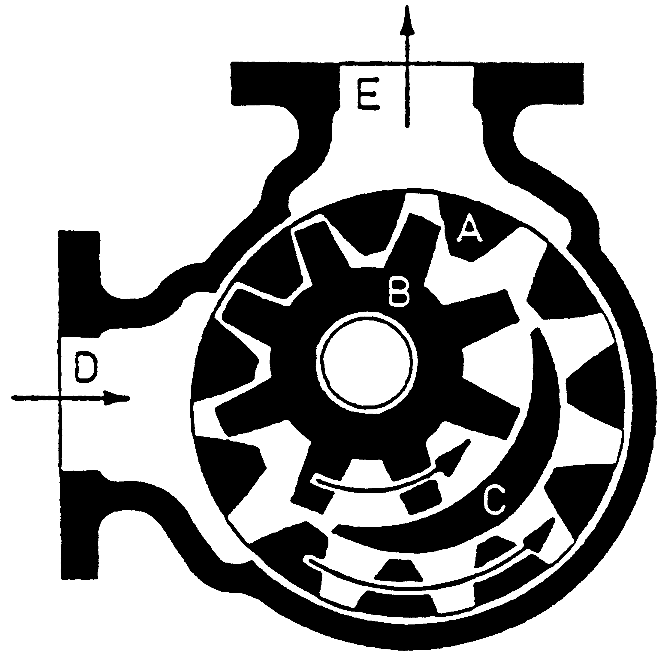
SECTION 3 - OPERATION 3.1DESCRIPTION
balance requiring only minimal torsional load to
The EBSRAY Internal Gear principle is based upon the
effectively follow the driving Outer Rotor.
use of an Outer Rotor 'A', idler gear, termed Inner Rotor
'B' and a crescent shaped spacer 'C' which is cast
integral with the Cover. Thus only two moving parts fulfil
this efficient displacement cycle. Power is applied to the
Outer Rotor 'A' and transmitted to the meshing idler or
Inner Rotor 'B'. The rotor teeth cells which are not involved in the meshing cycle are sealed by the crescent
3.2PUMPING PRINCIPLE
When rotation is started there is an increase in cell
volume as the teeth come out of mesh. This creates a
partial vacuum and the pressure differential thus created
initiates movement of the liquid through the inlet port 'D',
filling the teeth cells of the two displacement rotors.
When the tooth meshing withdrawal cycle is complete
and the tooth cell volume is filled with liquid, transfer to
3.3APPLICATIONS
the pressure or discharge side is effected as the liquid is carried past the crescent sealing member 'C'. This
The field of applications for Internal Gear rotary positive
sealing crescent establishes a labyrinth between the high
displacement pumps is extensive. These pumps are
and low pressure sides, minimising fluid slip. When the
used to handle many kinds of liquids over a wide range
teeth mesh on the pressure side, the liquid is forced from
of capacities and pressures, associated with viscous or
the teeth cells and flows through the discharge port 'E'.
non-viscous, hot or cold and corrosive or non-corrosive
A noteworthy feature of this simple pump principle is the
conditions. Accordingly material, speed and power
absence of high tooth contact pressures when compared
specifications vary and it is important to use such
with conventional gear pumps, many of which employ
equipment strictly adhering to the manufacturers'
costly external timing gears to minimise tooth wear. The
Inner Rotor 'B', or idler remains in almost hydraulic
3.4LUBRICATION 3.6OPERATIONAL CHECKS
Lubrication of the Inner Rotor bearing and Bracket
Inspect pump frequently during the first few hours of
Bearing (both are sleeve bearings) is dependent on the
operation for such conditions as excessive heating of
pumpages' lubricating qualities/material selection of the
bearings or stuffing box, vibration, unusual noises etc.
The Ball Bearing is lubricated at the time of assembly
3.7BYPASS VALVE
with a high quality lithium base grease. Replacement of this grease is normally only necessary when major
To protect the pump from overpressure due to
inadvertent shutting of discharge system, EBSRAY can
supply integral or inline Bypass Valves which are capable
3.5 STARTUP CHECKLIST
of circulating the entire pump output. The integral type Bypass Valve is mounted on the pump Cover and
bypasses pumpage from the pressure side to the inlet
The inline type Bypass Valve is installed in the pump
discharge line and normally returns to the inlet side of the
pump or back to tank. Fluid temperature will rise if
differential pressure is high and recirculating bypass
conditions are maintained for extended periods (particularly with integral Bypass Valve). The Bypass
Valve should be set on site, in accordance with the
predetermined pump and/or system differential pressure required. Refer separate instructions.
Do not start pump against closed discharge valve or with inlet (suction) valve throttled. Ensure bypass valve (if fitted) is operational and set to the correct pressure. Do not exceed system or pump design pressure as equipment failure could result.Do not run pump dry. Failure to remove air/vapour could prevent pump from priming and result in pump damage. SECTION 4 - MAINTENANCE CAUTION PRIOR TO ANY DISASSEMBLY OR SERVICE, 4.2PREPARATION FOR DISASSEMBLY VERIFY THAT ALL REQUIREMENTS OF STATUTORY REGULATIONS OR CODES ARE MET AND THAT
Obtain the appropriate Work Permit if required.
SPECIFIC SITE REQUIREMENTS ETC ARE
Isolate pump from liquids in inlet and discharge
SATISFIED.
lines, depressurise and purge out any toxic,
Some minor maintenance tasks and inspections can be
flammable, corrosive or air hardening liquids.
performed with the pump 'in line' so long as complete
isolation, depressurising and purging procedures have been completed. However for major maintenance it is
recommended that the pump be removed from the installation.
Mark relevant mating components for correct
4.1SPARE PARTS
When ordering spare parts, to ensure a minimum
4.3DISASSEMBLY
of delay and correct replacement to original specification ALWAYS quote the pump Serial
Note: Before proceeding, make sure Bracket is firmly
Number which is located on the nameplate of the
attached to baseplate or bench etc. to avoid
overbalancing when rotor is withdrawn. Mark relevant mating components to ensure correct replacement.
Advise the name, item number and quantity
If fitted, remove Bypass Valve assembly from Cover – Refer Section 5
Remove Lockscrews on both Inner and Outer
Release Grubscrews and unscrew Locknut from
Remove lubrication/cooling circulation harness
.For pumps fitted with EBSRAY Mechanical Seals: 4.4INSPECTION
Release Mechanical Seal Plate evenly to avoid
Inspect components for damage or excessive wear. Note
that typical wear of components in EBSRAY's rotary Internal Gear positive displacement pumps tend to
Remove access plug and rotate Shaft until Drivescrew is accessible, loosen Drivescrew 2 full
compensate each other and working clearances are to
some extent maintained by this compensation. If pump performance has been satisfactory, existing components
To facilitate removal of Cover, tapped extraction
although worn, may still have adequate service life and
holes are fitted. Remove Cover assembly complete with Inner Rotor. Care should be taken
could be used provided any burrs or sharp edges are
to prevent Inner Rotor sliding off Inner Rotor Pin.
removed prior to reassembly. Major refurbishing of the pump should be done in line
10. The Rotor/Shaft assembly can now be driven
through the pump from the drive end taking care to
with reconditioning to an 'as new' status as replacing or
repairing one component may have an effect on other components and the working clearances of the pump.
11. Remove Inner Race Lockring and Bracket Ball
4.5REASSEMBLY- PRELIMINARY
Remove Mechanical Seal components taking care
Ensure all parts are clean before assembly.
Ensure free running fit of Inner and Outer
Press out Inner Rotor Bearing and Rotor Bearing if
Fit lip seals to Inner and Outer Lockrings,
positioning sealing lip towards Bearing.
.For pumps fitted with packed glands:
a) Metallic: Press-fit, ensuring lubrication groove in
Standard packed glands require correct grade packing
Bearing is in the 12 'O'clock position. If the Bracket
for duty. A Lantern Ring is fitted acjacent to the Rotor
has a greaser hole, align lubrication groove with
Bearing for suction return and relief of packing pressure.
the greaser hole and drill through after fitting Bearing.
b) Carbon: The recommended method of fitting
To facilitate removal of Cover, tapped extraction
carbon Bearings is shrink-fitting. Press-fitting
complete with Inner Rotor. Care should be taken
Bearing. Fit Bearing flush with spigot face,
to prevent Inner Rotor sliding off Inner Rotor Pin.
ensuring lubrication groove in Bearing is in the 12 'O'clock position. Machine or ream to achieve
The Rotor/Shaft assembly can now be driven
correct clearance on Shaft ensuring squareness
through the pump from the drive end taking care to
10. Remove Inner Race Lockring and Bracket Ball
a) Metallic: Press-fit with Bearing flush with one side of Inner Rotor.
Using a suitable tool, remove Packing and Lantern ring.
Machine or ream to achieve required clearance on Inner Rotor Pin ensuring squareness and
Press out Inner Rotor Bearing and Rotor Bearing if
TABLE OF CLEARANCES
Ensure all lubrication/cooling circulation
a) Axial length of Inner Rotor, Outer Rotor teeth
and Cover crescent must be matched to within
b) Outer Rotor in Body diametral clearance. Note:
Gaskets, Seals and "O"rings at every overhaul,
If checking by feeler gauge method, allowance
or compensation must be made for eccentricity
4.6REASSEMBLY (Refer Drg No. CMP051)
ii) Clearances between Shaft and Bracket
TORQUE SETTINGS
iii) Lack of Bearing support at drive end
To measure clearance, insert feeler gauge at
two opposite measurement points 'X1'. Add the
two clearances together. This will give the
During reassembly, lubrication is required in some
diametral clearance 'X' for the two points.
areas. All lubrication in areas where it may come into contact with pumped product should be with a product compatible lubricant. The Bracket Ball Bearing and lockring Seals may be lubricated with
c) To check clearance between Inner Rotor and
any high quality lithium base grease suitable for the
Cover crescent, Inner Rotor should be held
operating conditions. (For pumps fitted with SJ Cover Plate only)
Using a new Cover Gasket, locate the SJ Cover Plate on the Cover with the Inner Rotor Pin bores in alignment and temporarily fasten the two together using bolts of the same diameter as the Cover bolts. After fastening Inner Roror Pin (Step 4) remove these temporary bolts.
Fit Inner Rotor Pin Gasket to the Inner Rotor Pin locating step.
Apply a suitable sealant (e.g. Loctite) to the Inner
be tapped on by using a drift on its inner ring.
Rotor Pin bore in the cover. Ensure sealant does
Tapping on the outer ring could damage the
not enter the Inner Rotor. Press Inner Rotor Pin
into Cover ensuring lubrication groove points
14. Lubricate outer lockring Lipseal and screw Outer
centrally towards crescent and adequate support is
given around the Inner Rotor Pin bore boss when pressure is applied.
15. Slide Ball Bearing locknut along Shaft through
Lipseal and tighten firmly using a suitable tool.
Place Inner Rotor Pin Spacer (if fitted) and Inner
Rotor Pin Washer over Inner Rotor Pin and lock Inner Rotor Pin Nut securely whilst maintaining
16. Replace lubrication/cooling circulation harness
lubrication groove location. Note: Use of a split
17. If fitted, reinstall Bypass Valve – Refer Section 5.
Fit Body to Bracket with Gasket between faces. Maintain correct inlet and discharge port
4.7ROTOR AXIAL CLEARANCE ADJUSTMENT
orientation, securely tighten in a uniform manner.
The Inner and Outer Lockrings when finally positioned
Insert Rotor/Shaft assembly ensuring Rotor Bearing
determine the Bracket Ball Bearing location within the
Bracket. As the Ball Bearing is positively locked to the
7. Fit Inner Rotor over Inner Rotor Pin in Cover
Shaft shoulder by the Bearing Locknut, the positioning of
assembly with flush side towards Cover, ensure
the Ball Bearing will control the Rotor axial clearance.
Fit Cover assembly to Body with Gasket between
faces, make sure the seal land of the Cover
a) A crank handle or other suitable arrangement
matches with the seal land in the pump Body. (This
should be affixed on the coupling end of the
seal land is diametrally opposite the centre of the
Rotor/Shaft assembly to facilitate rotating of the
Cover crescent). Lubricate pump elements through
pump port and check that Rotor/Shaft assembly
b) Screw Outer Lockring in a clockwise direction
whilst simultaneously rotating assembly. This
.For pumps fitted with EBSRAY mechanical seals:
enables sensing the rotor-cover point of contact ie. a slight drag is felt by hand.
Slide Circlip along Shaft ensuring gap in Circlip lines up with access hole. Take care to avoid
c) Mark Outer Lockring position relative to Bracket
i.e. establish a datum point for setting axial clearance.
10. Slide Circlip Retainer along Shaft until located
against Circlip (a suitable tube may help, keep drive
d) Back off Outer Lockring 180 degrees to
screw inline with access hole), tighten Drivescrew.
11. Insert Spring, Drivewasher, Rotating 'O'ring,
e) Reposition Outer Lockring to a point measured
Rotating Face, Stationary Face, Stationary 'O' ring
radially from the previously marked datum equal
and Mechanical Seal Plate. Note: Particular care
to the amount of desired axial clearance.
must be taken to avoid contamination of lapped
Note: For model HD600 5.14 mm radial movement on
seal surfaces by any foreign matter. All parts should
the O.D. of the Outer Lockring equals 0.025 mm axial
be lubricated before assembly and Drivepins must be located during assembly. Mechanical Seal Plate
movement of the Rotor/Shaft assembly. Refer Table of
.For pumps fitted with packed glands:
Example: Standard 'A' clearance 0.13 - 0.18 mm
Place Packing rings in position in accordance with
normal packing procedures. For standard square
Packing with one Lantern Ring, use eight (8) rings
is equivalent to 26.7 - 37.2 mm radial movement on the
of 12.7mm square Packing. For other types of packing refer to suppliers instructions.
10. Position Gland Plate and tighten by hand only.
f) Screw in Inner Lockring to lock hard against ball
11. Final adjustment is carried out during operation of
bearing. At this point, check for freedom of
pump. Packed glands, when adjusted correctly are
rotation of assembly. Axial clearance should
designed to have a very small amount of seepage.
If packing is too tight it will generate excessive heat,
g) Tighten Inner and Outer Lockring Lockscrews.
12. Lubricate Lipseal on Inner Lockring and slide
Lockring along Shaft, screw Lockring in until it protrudes approximately 4mm from thread on pump side.
13. Lubricate Bracket Ball Bearing. Fit Bearing to Shaft
and drive Bearing into position against Shaft shoulder using a suitable drift. Bearing should only
SECTION 5 - INTEGRAL BYPASS VALVES
5.1 GENERAL
It is advised that all gaskets be replaced whenever disassembled.
This Bypass Valve is intended for integral installation in EBSRAY's Internal Gear Pumps. The valve is mounted
Check Cap, Washer, Adjusting Screw and Locknut
in such a manner as to return liquid from the discharge
side of the pump to the inlet side of the pump when
differential pressure reaches or exceeds a preset level.
5.6 REASSEMBLY
The Bypass Valve is mounted with the Adjusting Screw pointing toward the inlet chamber of the pump.
(Refer Drg No. CMP051) 1. Screw Locknut onto Adjusting Screw and then
5.2 OPERATION
2. Fit Valve into Body, ensuring freedom of
The BYPASS VALVE is spring loaded and adjustable
within a pressure range determined by the actual spring used. EBSRAY can supply a variety of springs to suit
varying differential pressures. They are designed for liquid service and to provide pump and drive protection
from excessive differential pressures above specified
Fit Gasket to Cap, position Cap on Body ensuring
that the Adjusting Screw locates in the hole in the
Upon commissioning, the Bypass Valve should be
adjusted in accordance with the predetermined pump differential pressure required.
NOTE This may be achieved easily by screwing the
Adjusting Screw all the way in for positioning
and then backing off the Adjusting Screw to
5.3 MAINTENANCE PRIOR TO ANY DISASSEMBLY OR SERVICE,
Fasten Cap to Body by means of four Setscrews.
VERIFY THAT ALL REQUIREMENTS OF STATUTORY REGULATIONS OR CODES ARE MET AND THAT SPECIFIC SITE REQUIREMENTS ETC. ARE 5.7 ADJUSTMENT SATISFIED.
NOTE: Final adjustment is carried out after the valve is
Apart from Bypass Valve Body replacement, other
maintenance tasks and inspections can be carried out
For increased bypass pressure, rotate Adjusting
with the Bypass Valve fixed to the pump Cover, so long
Screw in clockwise direction ( i.e.screw in ). DO
as complete isolation, depressurising and purging have
NOT exceed pump or system design pressure.
For decreased bypass pressure, rotate Adjusting
5.4 DISASSEMBLY
3. Lock Adjusting Screw Lock Nut against Cap
immediately after any adjustment is made.
3. Release spring pressure by rotating Adjusting
After Adjstment is completed, fit Adjusting Screw
Remove the four Setscrews, affixing the Bypass
NOTE: Bypass valves characteristically exhibit three
distinct differential pressures during their operation :
Remove the Cap assembly complete with Adjusting
a) The set or 'cracking' pressure which occurs
when product initially begins to be bypassed
Remove Adjusting Screw and Llocknut from Cap.
Remove Spring Cap, Valve Spring and Valve from
b) Maximum differential pressure, which occurs
when the flow of the bypassed product passes through the bypass valve.
5.5 INSPECTION
c) Full flow differential pressure which occurs
Inspect Bypass Valve Body, particularly valve seat,
when all the product being pumped passes
for damage or wear. If required remove Bypass
It is important to ensure the above characteristics are
2. Check Valve for damage or deposits. Clean
thoroughly or replace Valve as required. If worn, or
understood fully in order to correctly apply and adjust the
if seat or Valve is damaged, lap cleaned/replaced
Inspect Bypass Valve Spring. Replace if broken or damaged.
SECTION 6 - TROUBLE SHOOTING 6.1 PUMP FAILS TO PRIME OR DELIVER LIQUID 6.3 EXCESSIVE POWER CONSUMPTION
1 Differential pressure higher than rating.
2 Liquid properties not as specified - check viscosity.
3 Rotating parts bind - check for proper clearances or
a) If motor driven, check speed, line voltage and
4 Bearings worn - inspect and replace as required.
b) If engine driven, check governor setting and
5 Obstructions in pipe lines, clogged strainers, partially
4 System discharge head too high - check system
head, friction losses and bypass valve setting.
5 Excessive inlet restrictions - check NPSH available
(inadequately sized inlet piping may cause high
friction losses,vapour pressure of liquid may be too
6.4 PUMP IS NOISY
high). Check with vacuum or compound gauge.
1 Cavitation is taking place - increase NPSH by:
6 Air leaks and/or air pockets in inlet line - check inlet
a) Removing inlet line restrictions created by:
7 Bypass valve open due to obstruction under seat of
(i) Inadequate pipe sizes / excessive line
(ii) Incorrect selection of valves, fittings etc.
8 Inlet filter/strainer blocked or leaking air.
(iii) Strainer not permitting free flow of liquid to
9 Pump cannot clear vapour due to excessive
b) Increasing static head in supply vessel.
6.2 LOW OUTPUT
2 Rotating parts bind - check for proper clearances.
3 Pump and driver misaligned - check coupling and
2 Entrained air or gases in liquid pumped.
3 Strainer offering excess resistance to flow.
4 Inlet and/or discharge pipes of insufficient diameter,
5 Bypass valve pressure setting too low - Increase
pressure by screwing in adjusting screw. DO NOT exceed pump or system design pressure, or overload motor etc.
7 Excess axial clearance setting of rotor to cover.
8 Excess clearances in pump due to wear.
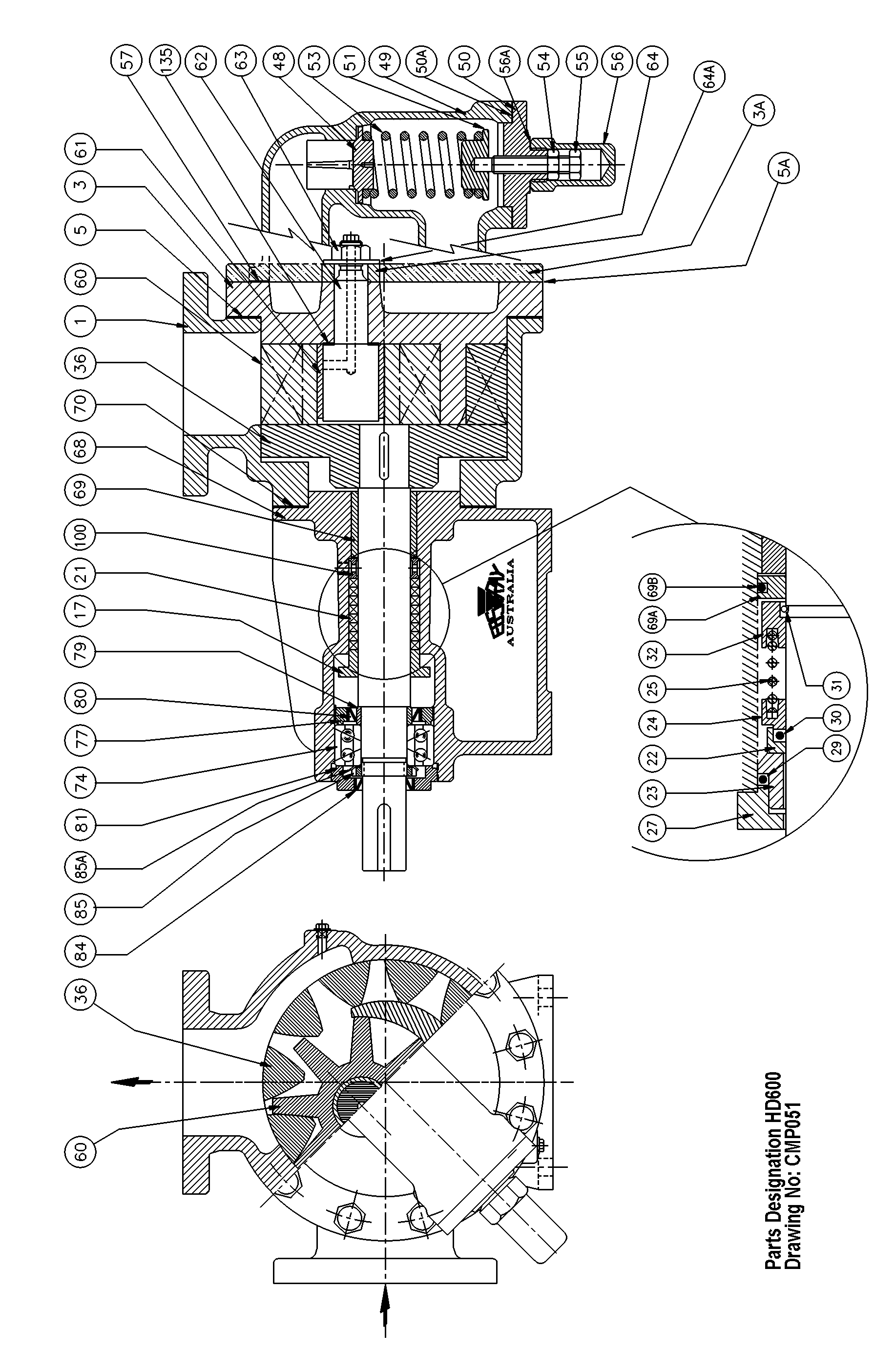
SECTION 7 - PARTS DESIGNATION
EBSRAY Internal Gear Pump Model HD600 Refer Drg No.: CMP051
CAT# .DESCRIPTION .QUANTITY 1.Body.1 3.Cover .1 3A .Cover Plate .1 5.Cover Gasket.1 5A .Cover Plate Gasket .1 17.Gland Plate .1 21.Gland Packing .2.14 metres x 12.7mm square 22.Mechanical Seal Rotating Face .1 23.Mechanical Seal Stationary Face.1 24.Mechanical Seal Drive Washer .1 25.Mechanical Seal Spring.1 27.Mechanical Seal Plate .1 29.Mechanical Seal Stationary 'O'ring.1 30.Mechanical Seal Rotating 'O'ring .1 31.Mechanical Seal Circlip .1 32.Mechanical Seal Circlip Retainer .1 36.Outer Rotor on Shaft assembly.1 48.Bypass Valve .1 49.Bypass Valve Body .1 50.Bypass Valve Body Cap .1 50A .Bypass Valve Cap Gasket.1 51.Bypass Valve Spring Cap.1 53.Bypass Valve Spring .1 54.Bypass Valve Lock Nut.1 55.Bypass Valve Adjusting Screw.1 56.Bypass Valve Adjusting Screw Cap .1 56A .Gasket - Adjusting Screw Cap .1 57.Bypass Valve Gasket .2 60.Inner Rotor .1 61.Inner Rotor Bearing .1 62.Inner Rotor Pin.1 63.Inner Rotor Pin Nut .1 64.Inner Rotor Pin Washer.1 64A .Inner Rotor Pin Spacer .1 68.Bracket.1 69.Rotor Bearing.1 69A .Extraction Washer .1 69B .Extraction Washer 'O'ring.1 70.Bracket Gasket .1 74.Bracket Ball Bearing .1 77.Bracket Ball Bearing Inner Lockring.1 79.Bracket Ball Bearing Inner Spacer .1 80.Bracket Ball Bearing Inner Seal .1 81.Bracket Ball Bearing Outer Lockring .1 84.Bracket Ball Bearing Outer Seal.1 85.Bracket Ball Bearing Locknut .1 85A .Tabwasher .1 100.Lantern Ring .1 135.Inner Rotor Pin Gasket .1 NOTE:.This list covers various pump configurations, before ordering parts, please check
the requirements for your particular pump. Ensure that Pump SERIAL No is quoted when ordering parts.
Aspirin and Decompression Diving The following text taken from internet is quite illuminating. It explains how Aspirin and related drugs affect blood chemistry and the possible effects on divers. As for ibuprofen while diving, 800 mg every 4 hours or even as a pre-dive ritual seems excessive, as you probably only need one 200 mg tablet in a 24-hour period. God almighty you guys must
 INSTALLATION, OPERATION & MAINTENANCE
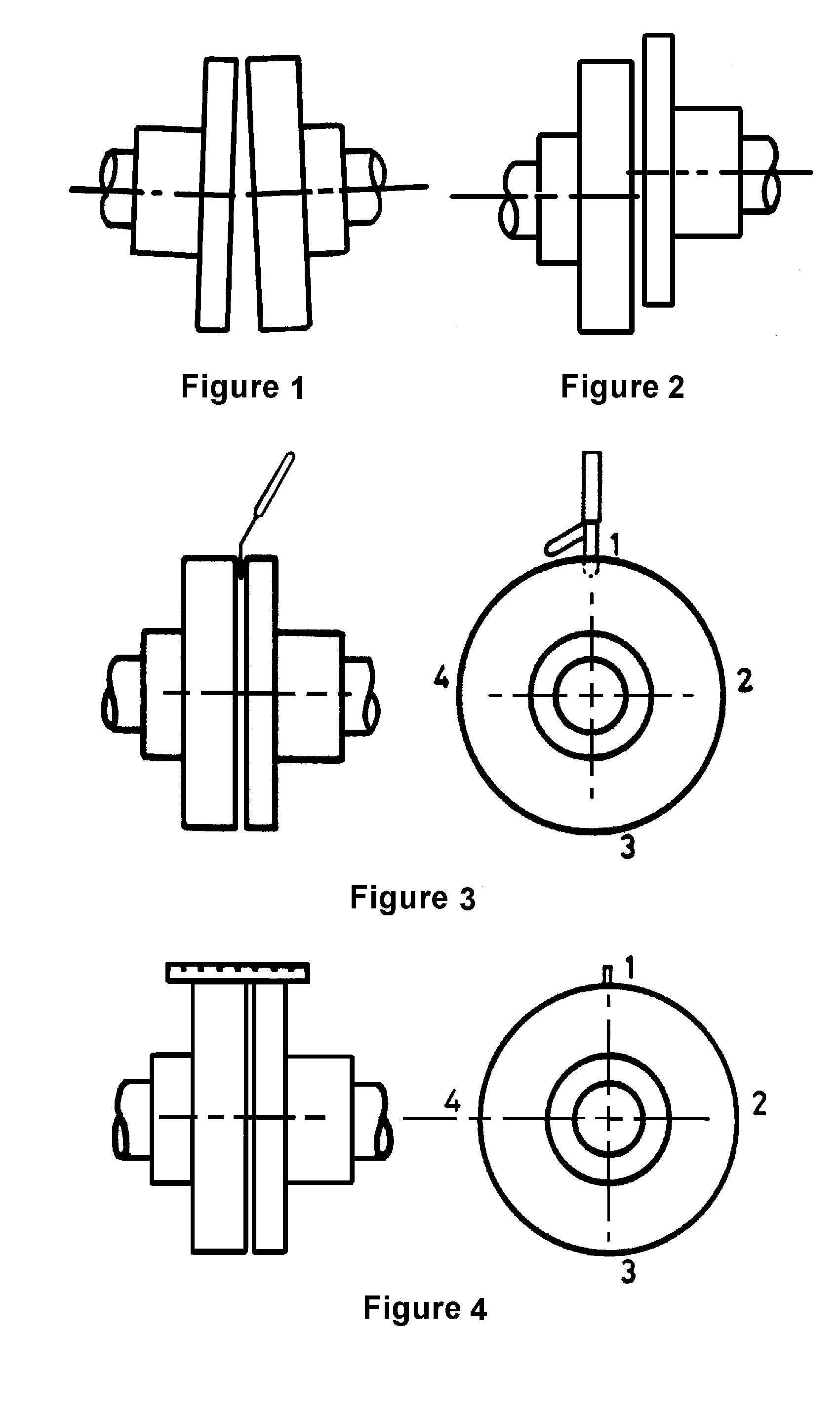
 2.5 ALIGNMENT
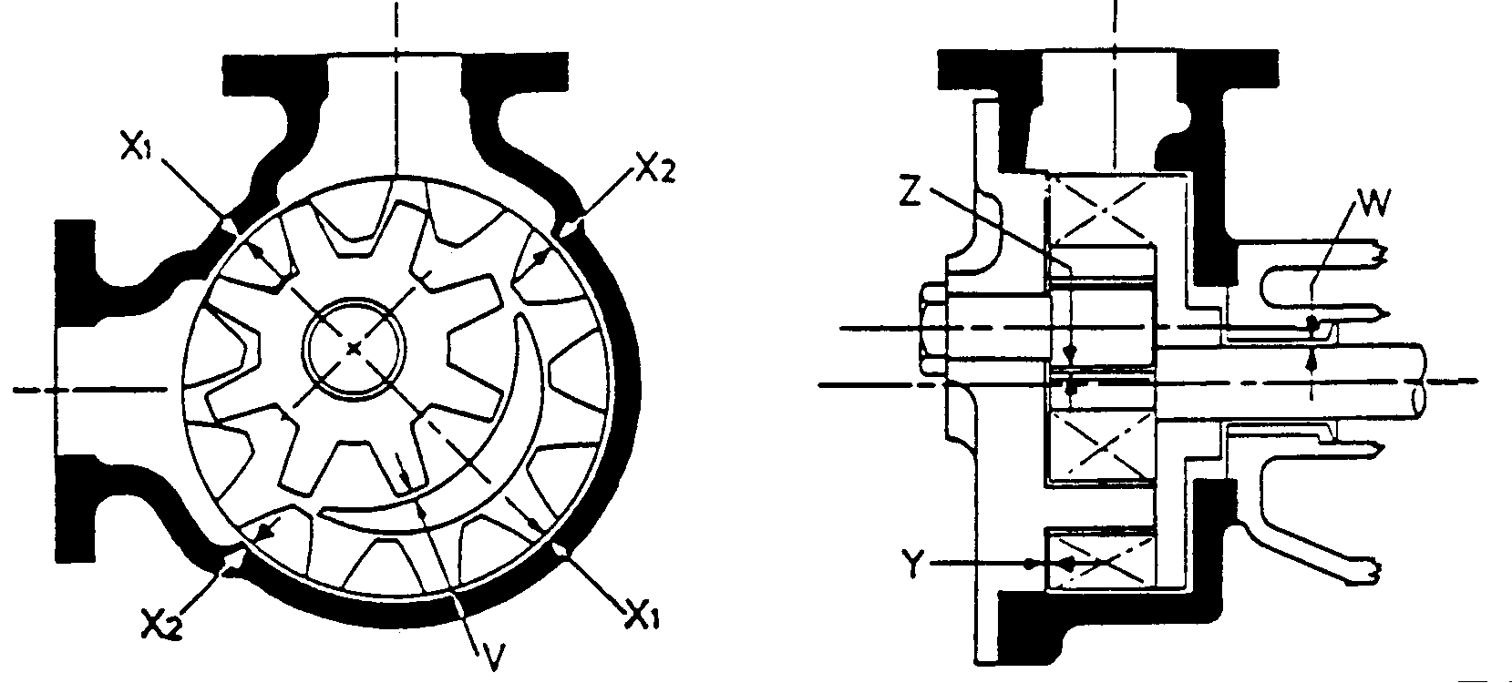
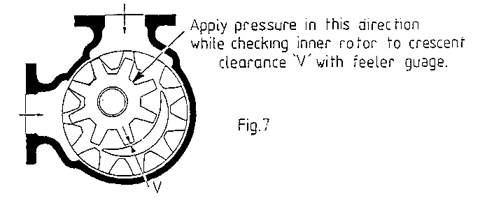 TABLE OF CLEARANCES