Thank you, it's cool. Used for the first time because only then was the right drug. Very revealing detail: ordered Express shipping to get the order within 3 hours because didn't know how to get the order faster https://africarx.co.za/buy-cialis-south-africa.html The drug is authentic exactly. Consistent with the stated prices the Staff is knowledgeable.
Semic.cz
DS26LS32CDS26LS32MDS26LS32ACDS26LS33CDS26LS33MDS26LS33AC
DS26LS32C DS26LS32M DS26LS32AC DS26LS33CDS26LS33M DS26LS33AC Quad Differential LineReceivers
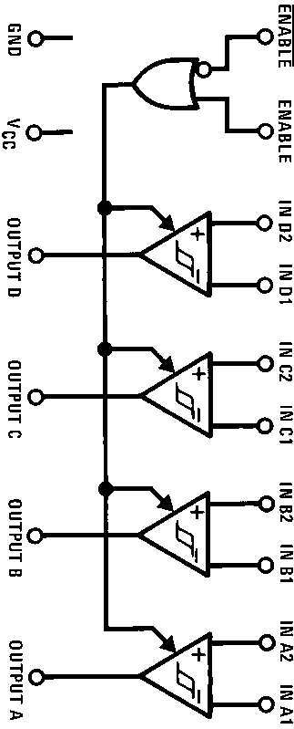
The DS26LS32 and DS26LS32A are quad differential line
High differential or common-mode input voltage ranges
receivers designed to meet the RS-422 RS-423 and Feder-
of g7V on the DS26LS32 and DS26LS32A and g15V
al Standards 1020 and 1030 for balanced and unbalanced
g 0 2V sensitivity over the input voltage range on the
The DS26LS32 and DS26LS32A have an input sensitivity of
DS26LS32 and DS26LS32A g0 5V sensitivity on the
DS26LS33 and DS26LS33A have an input sensitivity of
DS26LS32 and DS26LS32A meet all requirements of
500 mV over the input voltage range of g15V
Both the DS26LS32A and DS26LS33A differ in function
from the popular DS26LS32 and DS26LS33 in that input
100 mV input hysteresis on the DS26LS32 and
pull-up and pull-down resistors are included which prevent
Each version provides an enable and disable function com-
mon to all four receivers and features TRI-STATE
TRI-STATE outputs with choice of complementary out-
with 8 mA sink capability Constructed using low power
put enables for receiving directly onto a data bus
Schottky processing these devices are available over thefull military and commerical operating temperature ranges
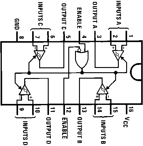
Note Input conditions may be any combination not defined for ENABLE
DS26LS32MJ DS26LS32ACM DS26LS32ACNDS26LS33CN DS26LS33MJ or DS26LS33ACNSee NS Package Number J16A M16A or N16A
Order Number DS26LS32MJ 883 DS26LS32MW 883
is a registered trademark of National Semiconductor Corporation
Absolute Maximum Ratings (Note 1)If Military Aerospace specified devices are required
please contact the National Semiconductor Sales
Office Distributors for availability and specifications
Derate cavity package 9 6 mW C above 25 C derate molded DIP package
Electrical Characteristics over the operating temperature range unless otherwise specified (Notes 2 3 and 4)
VOUT e VOH DS26LS32 DS26LS32A b7V s VCM s a7V
Note 1 ‘‘Absolute Maximum Ratings’’ are those values beyond which the safety of the device cannot be guaranteed They are not meant to imply that the deviceshould be operated at these limits The table of ‘‘Electrical Characteristics’’ provides conditions for actual device operation
Note 2 All currents into device pins are shown as positive all currents out of device pins are shown as negative all voltages are referenced to ground unlessotherwise specified All values shown as max or min are so classified on absolute value basis
Note 3 All typical values are VCC e 5V TA e 25 CNote 4 Only one output at a time should be shorted
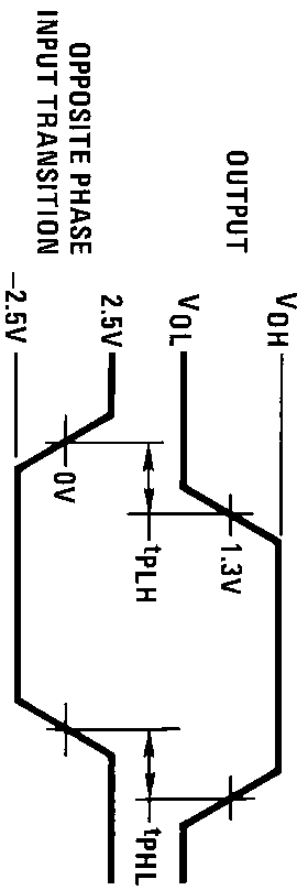
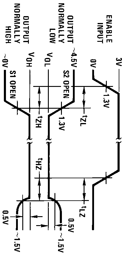
Switching Characteristics VCC e 5V TA e 25 C
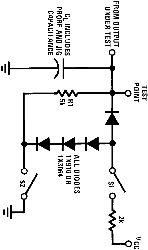
AC Test Circuit and Switching Time Waveforms
Note 2 S1 and S2 of load circuit are closed except where shown
Note 3 Pulse generator for all pulses Rate e 1 0 MHz ZO e 50X tr s 6 ns tf s 6 0 ns
Order Number DS26LS32MJ DS26LS33MJ DS26LS32MJ 883 or DS26LS33MJ 883
Physical Dimensions inches (millimeters) (Continued)
Order Number DS26LS32CN DS26LS32ACN DS26LS33CN or DS26LS33ACN
Physical Dimensions inches (millimeters) (Continued)
Order Number DS26LS32MW 883 or DS26LS33MW 883
NATIONAL’S PRODUCTS ARE NOT AUTHORIZED FOR USE AS CRITICAL COMPONENTS IN LIFE SUPPORTDEVICES OR SYSTEMS WITHOUT THE EXPRESS WRITTEN APPROVAL OF THE PRESIDENT OF NATIONALSEMICONDUCTOR CORPORATION As used herein
1 Life support devices or systems are devices or
2 A critical component is any component of a life
systems which (a) are intended for surgical implant
support device or system whose failure to perform can
DS26LS32CDS26LS32MDS26LS32ACDS26LS33CDS26LS33MDS26LS33AC
into the body or (b) support or sustain life and whose
be reasonably expected to cause the failure of the life
failure to perform when properly used in accordance
support device or system or to affect its safety or
with instructions for use provided in the labeling can
be reasonably expected to result in a significant injuryto the user
National does not assume any responsibility for use of any circuitry described no circuit patent licenses are implied and National reserves the right at any time without notice to change said circuitry and specifications
Calculating Confidence Intervals for the Number Needed to Treat Ralf Bender, PhD Department of Epidemiology and Medical Statistics, School of Public Health, University of Bielefeld, Bielefeld, Germany ABSTRACT: The number needed to treat (NNT) has gained much attention in the past years as a useful way of reporting the results of randomized controlled trials with a binaryoutcome. Def
PMI Risk Management Professional (PMI-RMP®) Your ability as a project risk manager to identify project risks along with plans to mitigate threats and capitalize on opportunities both on the job and through professional certification is becoming a necessary part of project management in today's fast-paced and highly technical workplace filled with risks. In this course, you will apply the ge
 DS26LS32CDS26LS32MDS26LS32ACDS26LS33CDS26LS33MDS26LS33AC
DS26LS32C DS26LS32M DS26LS32AC DS26LS33CDS26LS33M DS26LS33AC Quad Differential LineReceivers
The DS26LS32 and DS26LS32A are quad differential line
High differential or common-mode input voltage ranges
receivers designed to meet the RS-422 RS-423 and Feder-
of g7V on the DS26LS32 and DS26LS32A and g15V
al Standards 1020 and 1030 for balanced and unbalanced
g 0 2V sensitivity over the input voltage range on the
The DS26LS32 and DS26LS32A have an input sensitivity of
DS26LS32 and DS26LS32A g0 5V sensitivity on the
DS26LS33 and DS26LS33A have an input sensitivity of
DS26LS32 and DS26LS32A meet all requirements of
500 mV over the input voltage range of g15V
Both the DS26LS32A and DS26LS33A differ in function
from the popular DS26LS32 and DS26LS33 in that input
100 mV input hysteresis on the DS26LS32 and
pull-up and pull-down resistors are included which prevent
Each version provides an enable and disable function com-
mon to all four receivers and features TRI-STATE
TRI-STATE outputs with choice of complementary out-
with 8 mA sink capability Constructed using low power
put enables for receiving directly onto a data bus
Schottky processing these devices are available over thefull military and commerical operating temperature ranges
Note Input conditions may be any combination not defined for ENABLE
DS26LS32MJ DS26LS32ACM DS26LS32ACNDS26LS33CN DS26LS33MJ or DS26LS33ACNSee NS Package Number J16A M16A or N16A
Order Number DS26LS32MJ 883 DS26LS32MW 883
is a registered trademark of National Semiconductor Corporation
Absolute Maximum Ratings (Note 1)If Military Aerospace specified devices are required
please contact the National Semiconductor Sales
Office Distributors for availability and specifications
Derate cavity package 9 6 mW C above 25 C derate molded DIP package
Electrical Characteristics over the operating temperature range unless otherwise specified (Notes 2 3 and 4)
VOUT e VOH DS26LS32 DS26LS32A b7V s VCM s a7V
Note 1 ‘‘Absolute Maximum Ratings’’ are those values beyond which the safety of the device cannot be guaranteed They are not meant to imply that the deviceshould be operated at these limits The table of ‘‘Electrical Characteristics’’ provides conditions for actual device operation
Note 2 All currents into device pins are shown as positive all currents out of device pins are shown as negative all voltages are referenced to ground unlessotherwise specified All values shown as max or min are so classified on absolute value basis
Note 3 All typical values are VCC e 5V TA e 25 CNote 4 Only one output at a time should be shorted
DS26LS32CDS26LS32MDS26LS32ACDS26LS33CDS26LS33MDS26LS33AC
DS26LS32C DS26LS32M DS26LS32AC DS26LS33CDS26LS33M DS26LS33AC Quad Differential LineReceivers
The DS26LS32 and DS26LS32A are quad differential line
High differential or common-mode input voltage ranges
receivers designed to meet the RS-422 RS-423 and Feder-
of g7V on the DS26LS32 and DS26LS32A and g15V
al Standards 1020 and 1030 for balanced and unbalanced
g 0 2V sensitivity over the input voltage range on the
The DS26LS32 and DS26LS32A have an input sensitivity of
DS26LS32 and DS26LS32A g0 5V sensitivity on the
DS26LS33 and DS26LS33A have an input sensitivity of
DS26LS32 and DS26LS32A meet all requirements of
500 mV over the input voltage range of g15V
Both the DS26LS32A and DS26LS33A differ in function
from the popular DS26LS32 and DS26LS33 in that input
100 mV input hysteresis on the DS26LS32 and
pull-up and pull-down resistors are included which prevent
Each version provides an enable and disable function com-
mon to all four receivers and features TRI-STATE
TRI-STATE outputs with choice of complementary out-
with 8 mA sink capability Constructed using low power
put enables for receiving directly onto a data bus
Schottky processing these devices are available over thefull military and commerical operating temperature ranges
Note Input conditions may be any combination not defined for ENABLE
DS26LS32MJ DS26LS32ACM DS26LS32ACNDS26LS33CN DS26LS33MJ or DS26LS33ACNSee NS Package Number J16A M16A or N16A
Order Number DS26LS32MJ 883 DS26LS32MW 883
is a registered trademark of National Semiconductor Corporation
Absolute Maximum Ratings (Note 1)If Military Aerospace specified devices are required
please contact the National Semiconductor Sales
Office Distributors for availability and specifications
Derate cavity package 9 6 mW C above 25 C derate molded DIP package
Electrical Characteristics over the operating temperature range unless otherwise specified (Notes 2 3 and 4)
VOUT e VOH DS26LS32 DS26LS32A b7V s VCM s a7V
Note 1 ‘‘Absolute Maximum Ratings’’ are those values beyond which the safety of the device cannot be guaranteed They are not meant to imply that the deviceshould be operated at these limits The table of ‘‘Electrical Characteristics’’ provides conditions for actual device operation
Note 2 All currents into device pins are shown as positive all currents out of device pins are shown as negative all voltages are referenced to ground unlessotherwise specified All values shown as max or min are so classified on absolute value basis
Note 3 All typical values are VCC e 5V TA e 25 CNote 4 Only one output at a time should be shorted
 Switching Characteristics VCC e 5V TA e 25 C
AC Test Circuit and Switching Time Waveforms
Note 2 S1 and S2 of load circuit are closed except where shown
Note 3 Pulse generator for all pulses Rate e 1 0 MHz ZO e 50X tr s 6 ns tf s 6 0 ns
Switching Characteristics VCC e 5V TA e 25 C
AC Test Circuit and Switching Time Waveforms
Note 2 S1 and S2 of load circuit are closed except where shown
Note 3 Pulse generator for all pulses Rate e 1 0 MHz ZO e 50X tr s 6 ns tf s 6 0 ns
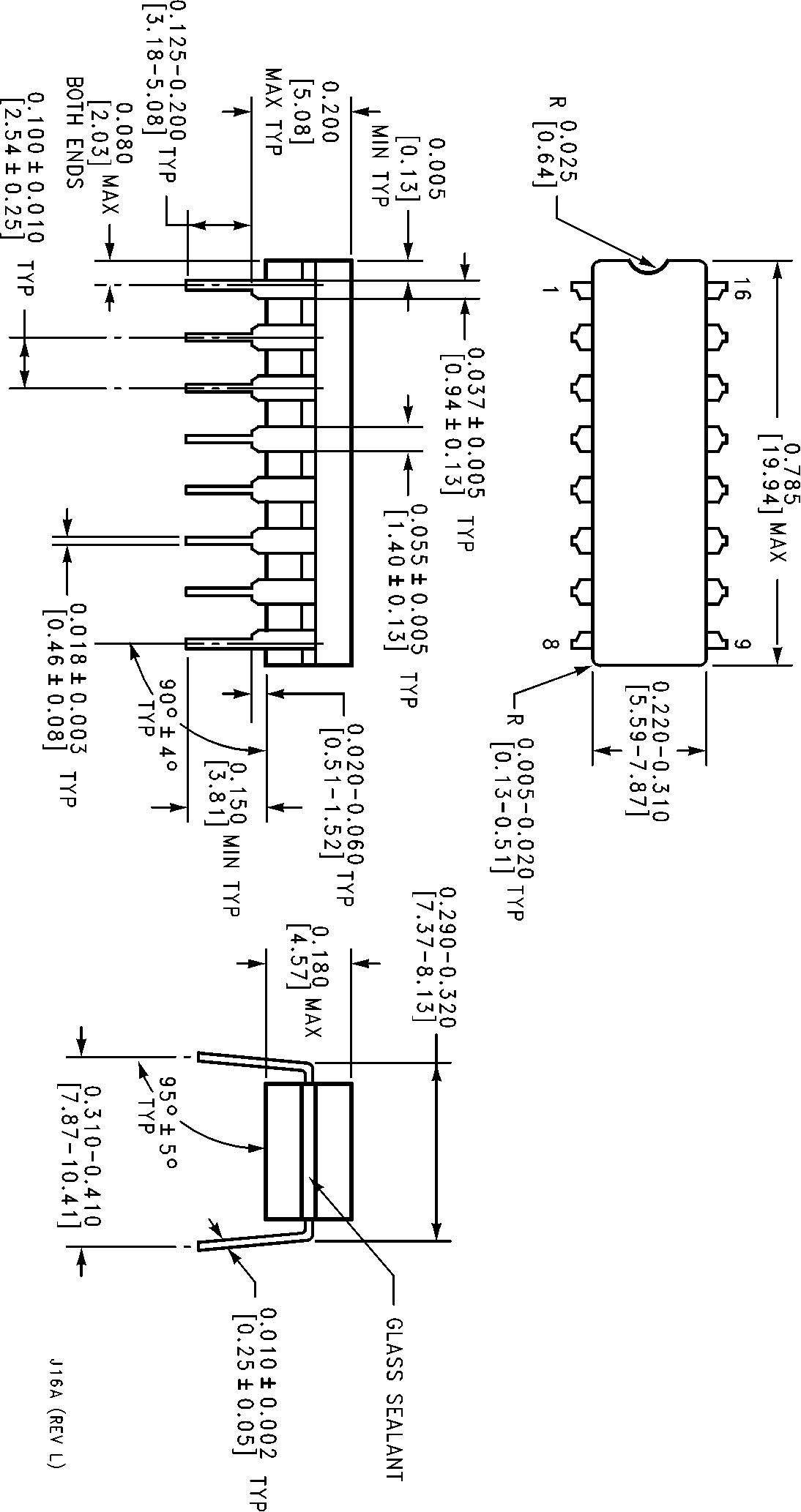
 Order Number DS26LS32MJ DS26LS33MJ DS26LS32MJ 883 or DS26LS33MJ 883
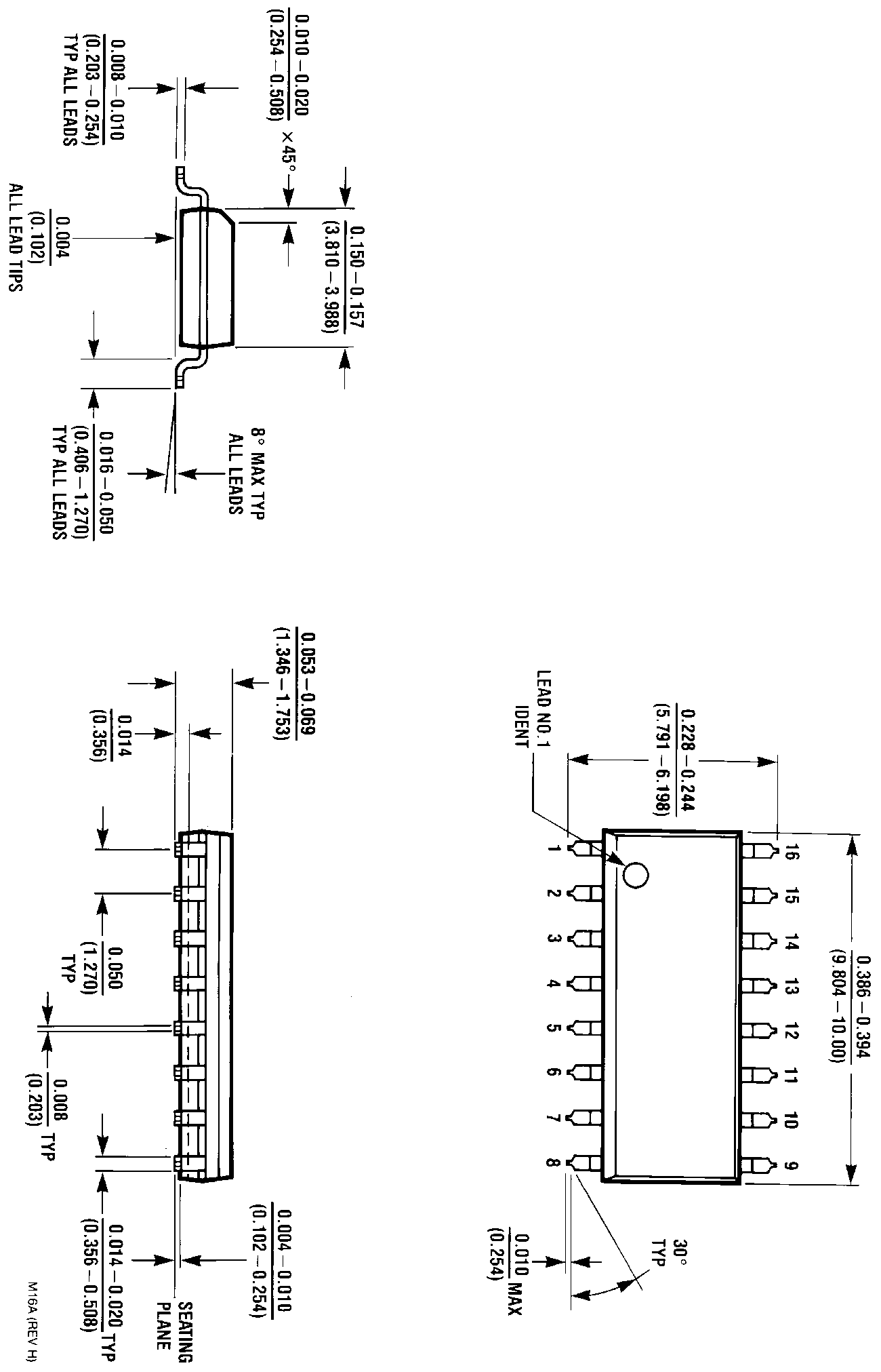
 Physical Dimensions inches (millimeters) (Continued)
Order Number DS26LS32CN DS26LS32ACN DS26LS33CN or DS26LS33ACN
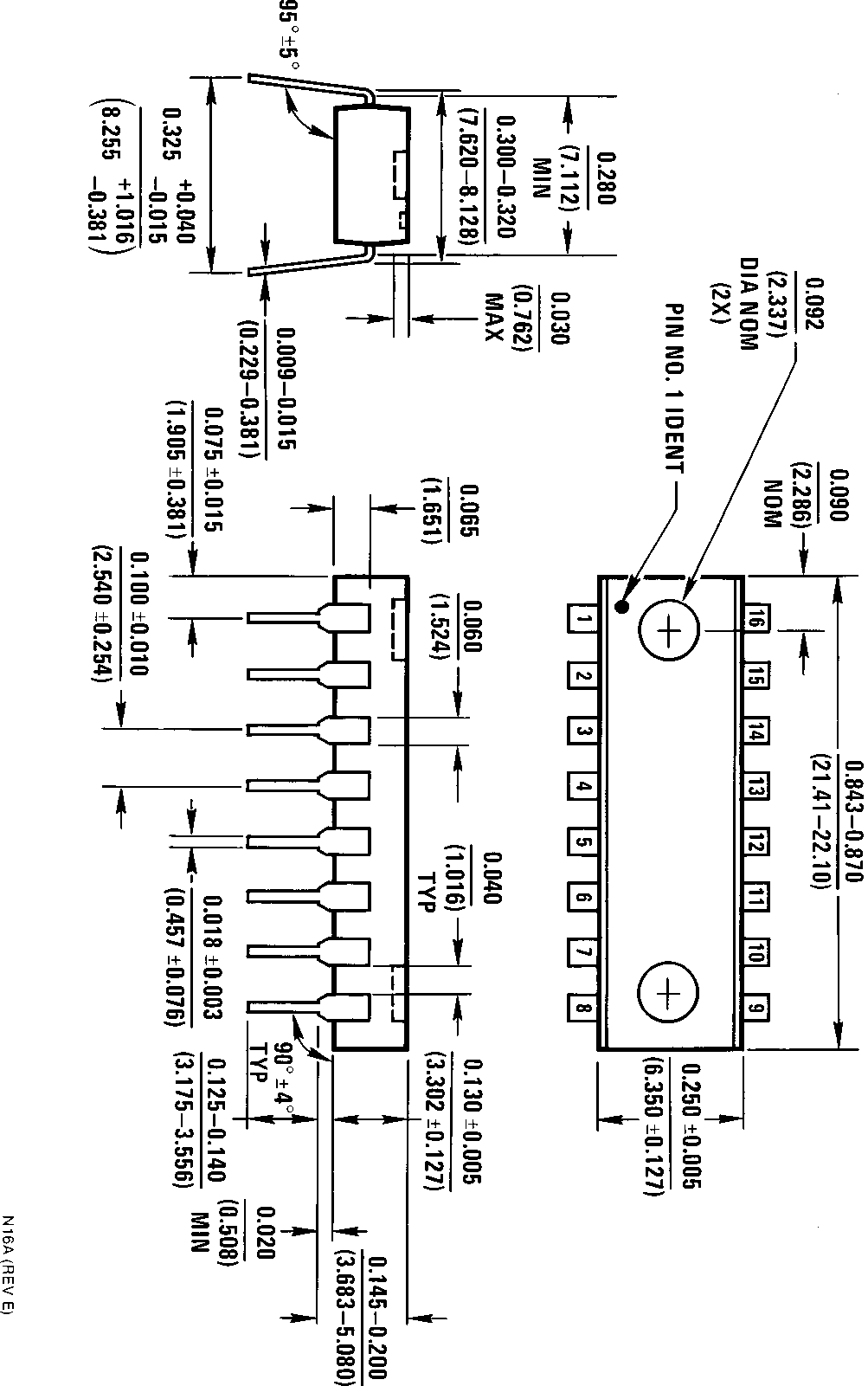
Physical Dimensions inches (millimeters) (Continued)
Order Number DS26LS32CN DS26LS32ACN DS26LS33CN or DS26LS33ACN
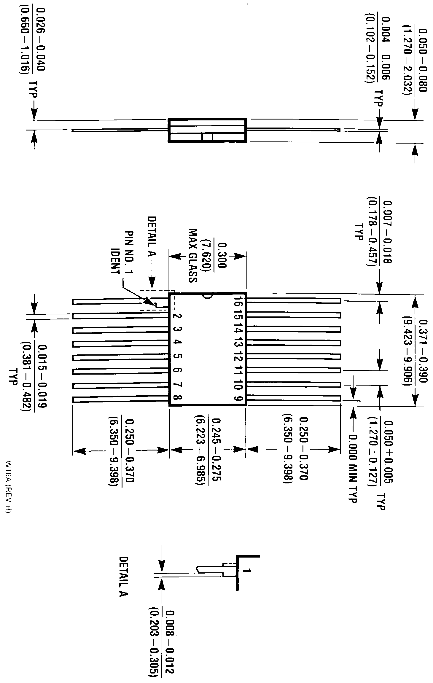
 Physical Dimensions inches (millimeters) (Continued)
Order Number DS26LS32MW 883 or DS26LS33MW 883
NATIONAL’S PRODUCTS ARE NOT AUTHORIZED FOR USE AS CRITICAL COMPONENTS IN LIFE SUPPORTDEVICES OR SYSTEMS WITHOUT THE EXPRESS WRITTEN APPROVAL OF THE PRESIDENT OF NATIONALSEMICONDUCTOR CORPORATION As used herein
1 Life support devices or systems are devices or
2 A critical component is any component of a life
systems which (a) are intended for surgical implant
support device or system whose failure to perform can
DS26LS32CDS26LS32MDS26LS32ACDS26LS33CDS26LS33MDS26LS33AC
into the body or (b) support or sustain life and whose
be reasonably expected to cause the failure of the life
failure to perform when properly used in accordance
support device or system or to affect its safety or
with instructions for use provided in the labeling can
be reasonably expected to result in a significant injuryto the user
National does not assume any responsibility for use of any circuitry described no circuit patent licenses are implied and National reserves the right at any time without notice to change said circuitry and specifications
Physical Dimensions inches (millimeters) (Continued)
Order Number DS26LS32MW 883 or DS26LS33MW 883
NATIONAL’S PRODUCTS ARE NOT AUTHORIZED FOR USE AS CRITICAL COMPONENTS IN LIFE SUPPORTDEVICES OR SYSTEMS WITHOUT THE EXPRESS WRITTEN APPROVAL OF THE PRESIDENT OF NATIONALSEMICONDUCTOR CORPORATION As used herein
1 Life support devices or systems are devices or
2 A critical component is any component of a life
systems which (a) are intended for surgical implant
support device or system whose failure to perform can
DS26LS32CDS26LS32MDS26LS32ACDS26LS33CDS26LS33MDS26LS33AC
into the body or (b) support or sustain life and whose
be reasonably expected to cause the failure of the life
failure to perform when properly used in accordance
support device or system or to affect its safety or
with instructions for use provided in the labeling can
be reasonably expected to result in a significant injuryto the user
National does not assume any responsibility for use of any circuitry described no circuit patent licenses are implied and National reserves the right at any time without notice to change said circuitry and specifications